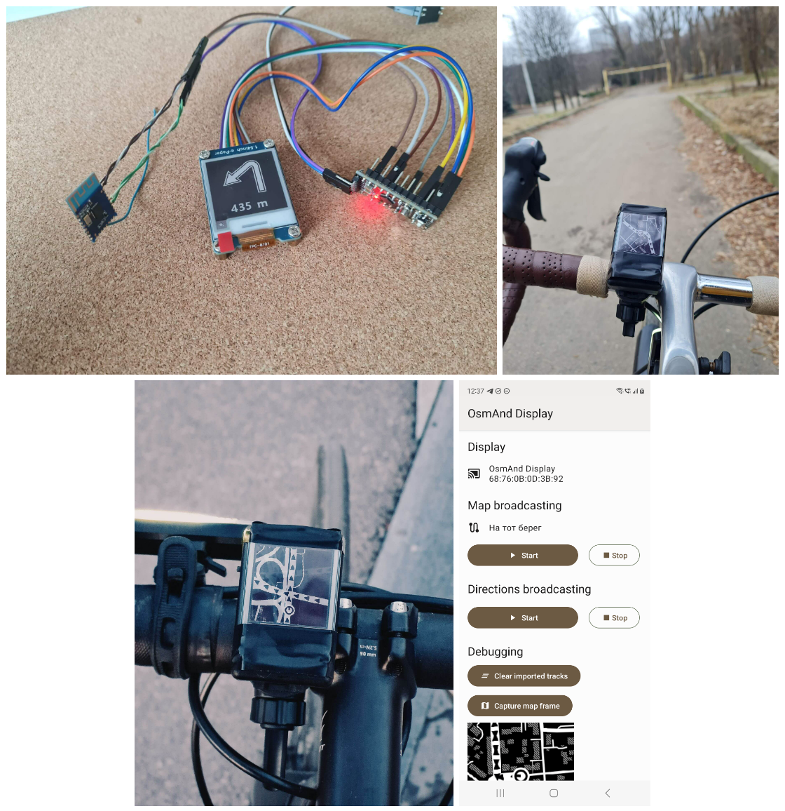
Bike navigation display: Making of
I've made a simple wireless display that helps me navigate through my bike rides.
The final result is described at the project page. In this article, I tell how it was built and highlight all the nuances.
Motivation
I truly enjoy riding my bicycle. Although I usually choose a well known route, sometimes the spirit of exploration makes me draw a route through the area I've never visited before. I can't remember all the turns in advance, so I have to rely on track navigation, for which I use OsmAnd. But this means I need to get directions somehow.
I have no bike computer and I also don't want to mount my phone on the handlebar – the phone gets discharged very quick with the screen constantly turned on, and the setup looks unreliable. I neither want to ride with headphones nor turn on loud voice navigation – I don't want to lose a direction because of the wind, neither to draw extra attention.
What I wanted was a visual navigation helper, power efficient and easily visible under the sun.
Inspiration
I've seen two projects which looked like the thing I needed: Smart Halo and Beeline 2. The LED circle in Smart Halo looks minimalistic and fancy, but I doubted such an indicator can provide enough information on track navigation – it is more suitable for a compass application.

Beeline 2 track navigation seemed like an ultimate solution, but back then I thought that the live map is an overkill, and simple step-by-step directions would be enough.

Prototype
It is wise to start something complicated with a prototype. It may look ugly, and the code may be messed up, but your goal at this stage is to prove that the idea makes sense and is doable.
My feature scope for the prototype was the following:
- The display shows step-by-step directions received from the OsmAnd Android app;
- It is connected to the phone via Bluetooth.
As you can see, at this stage there is nothing about the power, case or speed.
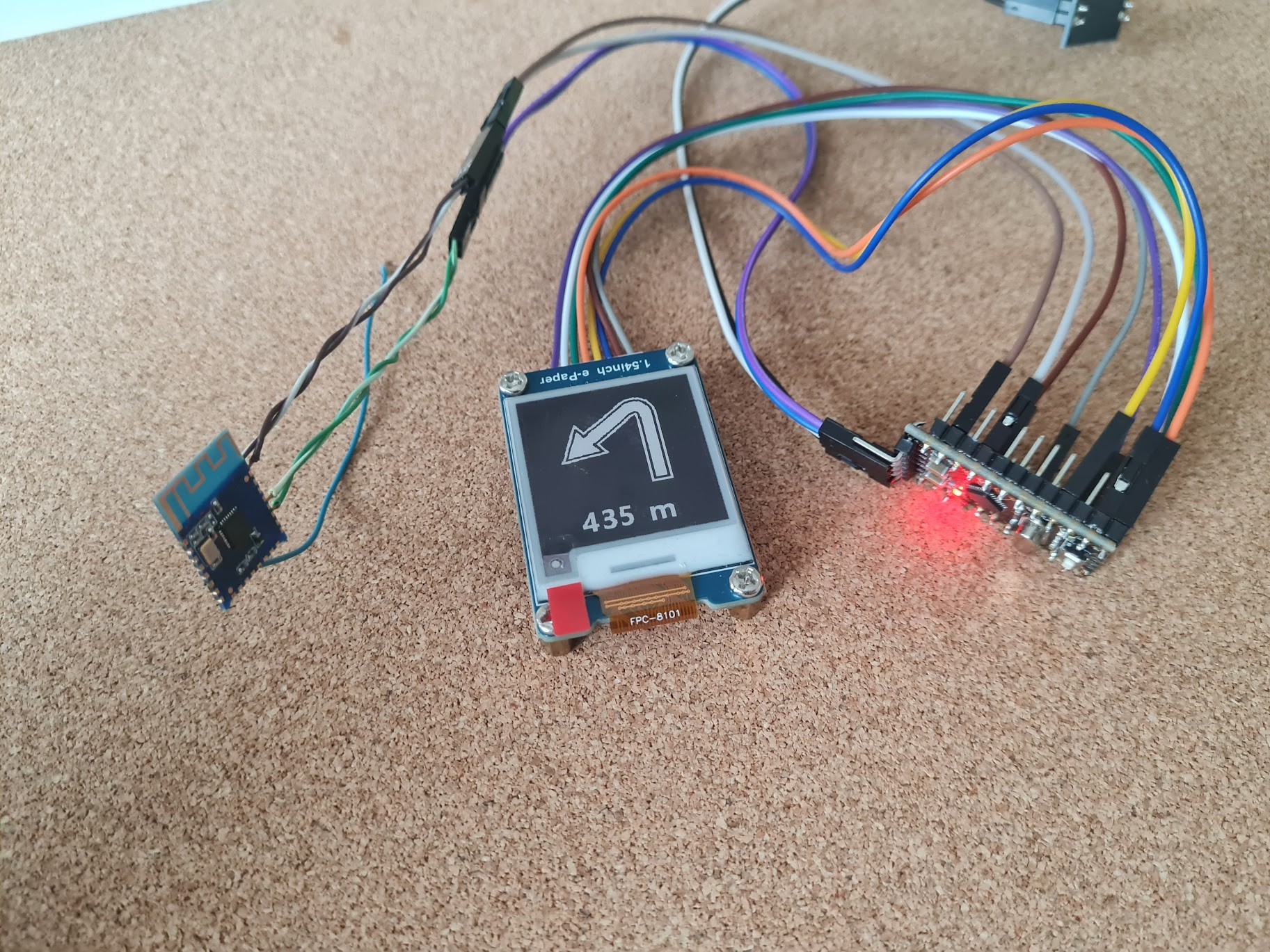
For the prototype, I've collected the following components:
- Waveshare 1.54 inch e-Paper display;
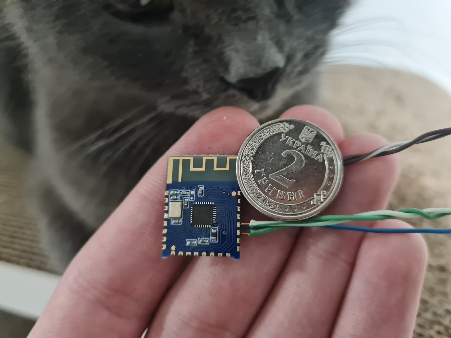
- JDY-23 Bluetooth Low Energy serial module;
- Arduino Pro Mini;
- AMS1117 3 V voltage stabilizer for the BLE module.
Dealing with the display
The first thing was to get used to the e-ink display. The thing happened to be extremely slow. I first thought it was due to the SPI speed, but it was the refresh sequence that takes 15 seconds in the black-white-red mode. The Waveshare demo code for this display was poor and didn't have partial refresh methods or any other options to speed up the refresh, so for two days I was desperate. Then I tried to use the code for the black-white version of the display with almost no hope, but it actually worked. In the black-white demo code were partial refresh methods as well as it contained a faster refresh sequence – 4 seconds instead of 15. The code used commands not described in the display datasheet, which made me think that the display uses a common controller with a rich set of capabilities, but the only problem is that you can't find the comprehensive documentation for it.
I ended up with prettifying the display library and removing all the redundant code from it. My sandbox code was able to clean the screen, control the sleep mode, draw bitmaps with horizontal mirroring from the EPROM and inverse colors.
Getting navigation directions from OsmAnd
Luckily, OsmAnd provides an API for external apps allowing to get navigation updates. When the navigation is active, the navigator broadcasts step-by-step directions to all the subscribers. The direction contains the next turn information: a type of the turn and a distance in meters to it. For bicycle navigation, 9 turn types need to be handled.
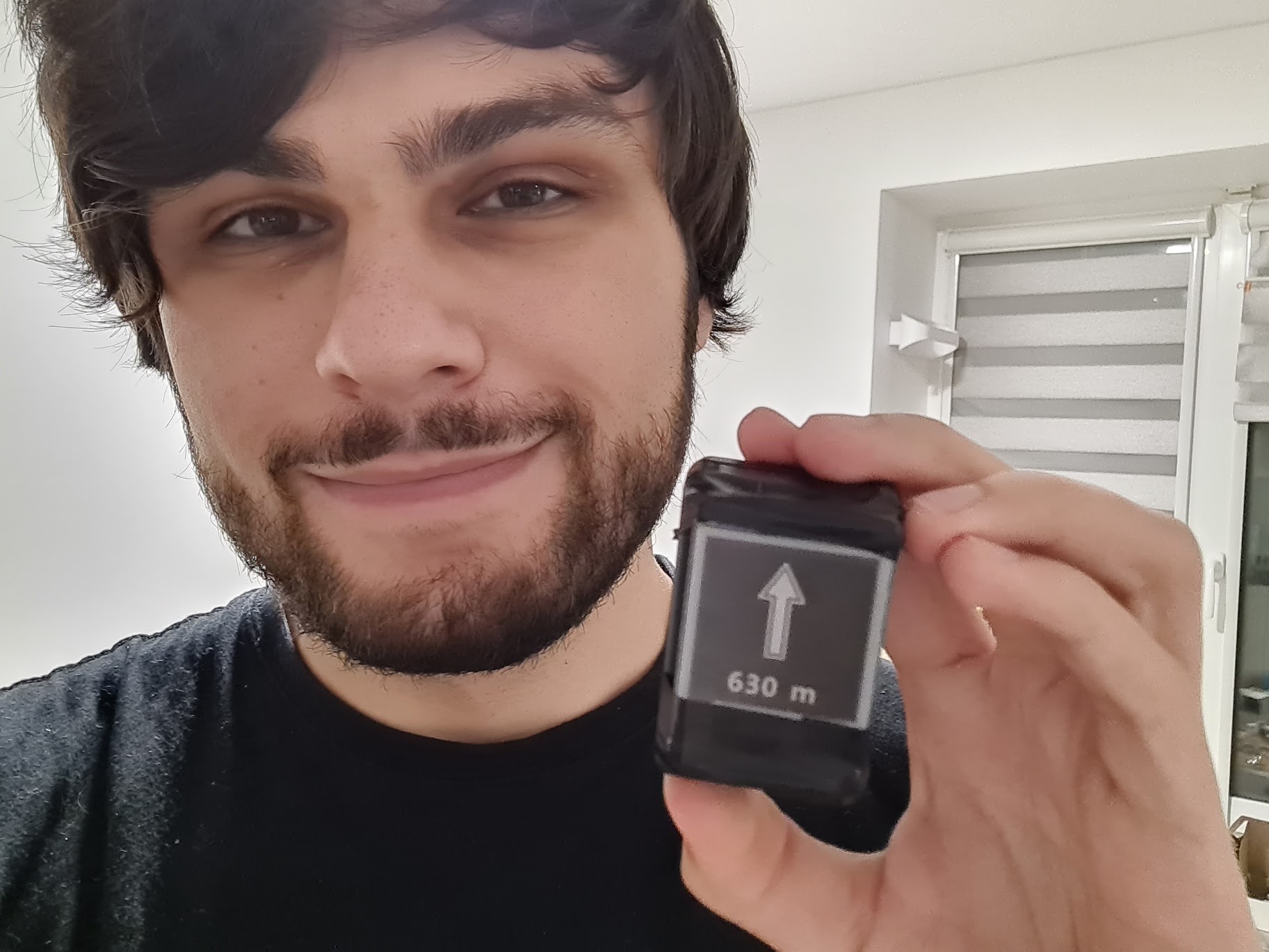
Implementing directions display
I prepared five 1-bit arrow images taken from the Noun Project icon collection. Together with horizontal mirroring, they can show 11 possible bike navigation turn types:
- Continue going forward;
- Slight left/right turn;
- Regular left/right turn;
- Sharp left/right turn;
- Left/right U-turn (what if I decide to ride on Cyprus one day, who knows).
The images were converted to C arrays with Image2Lcd and included to the Arduino EPROM using the PROGMEM directive.
The turn distance needed to be shown as well. The font embedded into the display library sucks – it is too small, too thin and it is also monospaced. I converted the Segoe UI Bold 36px font with only numbers and Latin letters to C arrays with TheDotFactory and included it into the EPROM as well. All the text painting was removed from the display library and re-implemented with EPROM and variable character width support. The result text appearance worth it.
Setting up the BLE serial
JDY-23 BLE module setup is pretty straightforward, the module is well documented. The important thing is not to overheat the board contact sites when soldering wires to it.
The module was connected to the Arduino serial pins while the board itself was connected through the 3 V stabilizer. The only thing you need to include to the code is to omit any incoming strings started with "+", as the module sends "+CONNECTED", "+DISCONNECTED" and other status messages to the port. I tested the serial connection with the Serial Bluetooth Terminal Android app, and it worked very well.
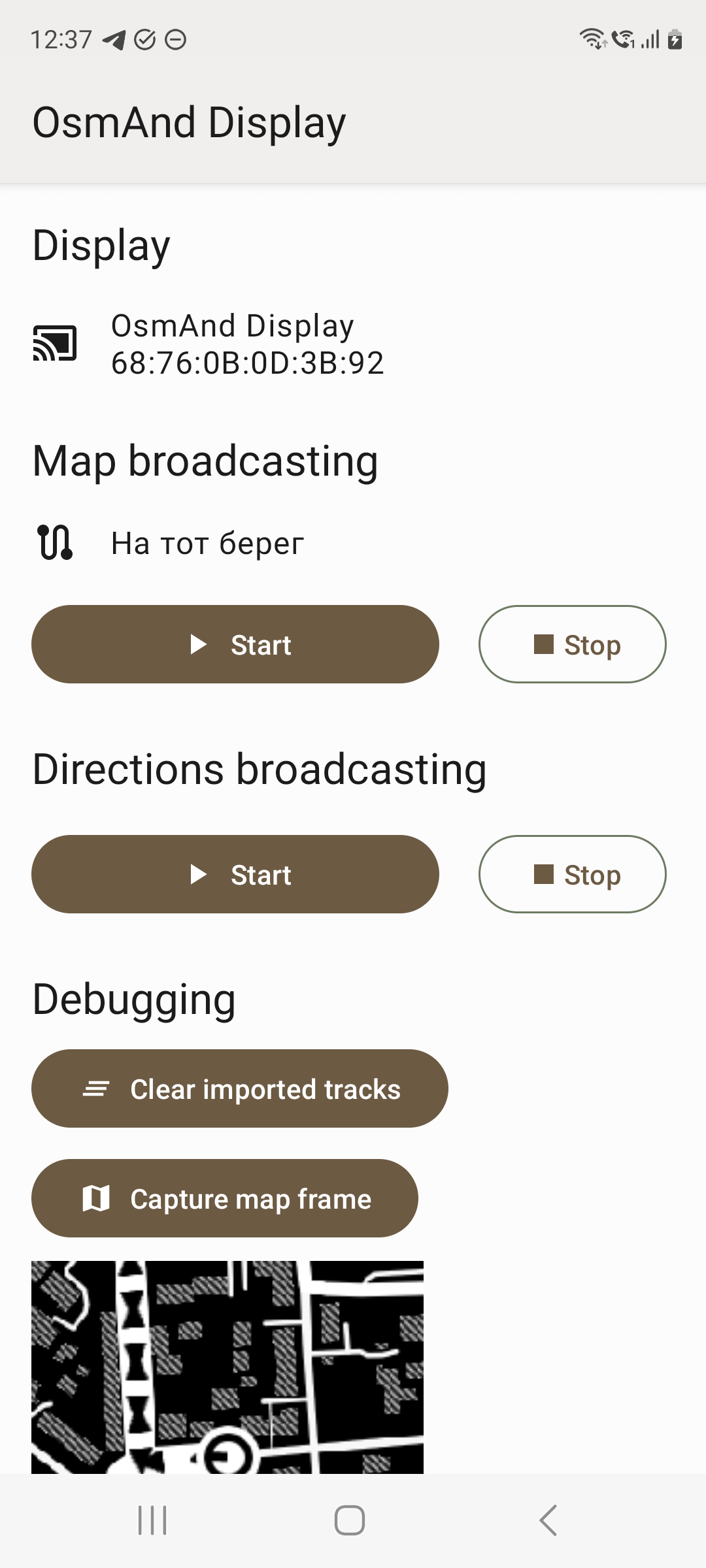
Implementing the Android app
For the direction broadcasting app, I used a foreground service and a minimal UI to control it. To connect to the display, Android's CompanionDeviceManager and BLESSED BLE library are used. I'm glad that there were no problems with the connection, although from the native Android documentation it looked as a mess.
To control the directions flow, I used one of my favorite tools– RxJava. In this project, I first met backpressure and parallelism factor of flatMap, which was interesing to learn. The stream was set up not to flood the display with outdated directions, as OsmAnd may send them faster than the display can show.
Testing and tweaking
I spent a few days to test the prototype and fix the bugs. Here OsmAnd needs to be appreciated one more time, as it has navigation simulation in the developer options.
I added partial display refresh, so in 4 draws from 5 the direction is shown a bit faster. Furthermore, I tweaked the directions stream in the app a lot to achieve the optimal response time and included OsmAnd voice navigation directions stream into it to get more info. The device seemed working well.
But at that stage I began to doubt how useful these directions would be. There were three worrying issues:
- OsmAnd sends the direction updates not as frequent as I expected. Even with step-by-step and voice navigation directions stream combined, you may go for hundreds of meters without any update and only get one when you are already too close to the turn;
- The display needs 4 seconds to display a direction, which means, that, depending on your speed, once you see a new direction you are already 20–40 meters off;
- When simulating a turn on a complicated crossing, the received direction wasn't too helpful as there were many ways that can be described as "turn slightly right".
Anyway, I decided that it needs testing on a bike, so I need to make the first portable version.
First version. Portable display of OsmAnd directions. Disappointment
To make the prototype portable, I needed to add a battery, reduce the power consumption and somehow put it into a mountable case.
The following components were added to the project:
- 300 mAh Li-Po battery;
- TP4056 charging module with a microUSB connector;
- Switch;
- General purpose plastic case.
I adjusted the current on the charging module with a resistor and connected it to the circuit along with the battery through the switch.
To reduce the power consumption, I removed LEDs from the modules and introduced the Arduino software frequency divider through the Gyver Power library. Instead of 16 MHz it was running at only 4, which saved a few milliamps of current and didn't affect the speed significantly, as the display refresh was still the bottleneck.
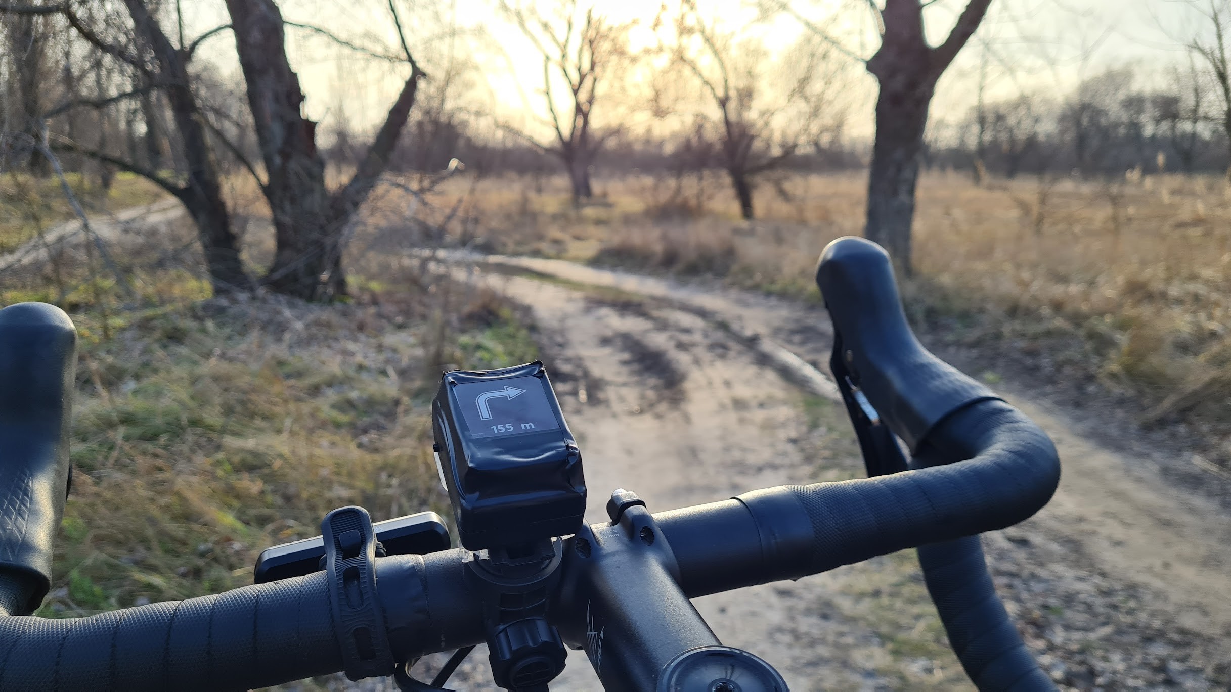
The case I purchased had too little volume to fit everything inside, so the bulky display ended up mounted outside the case. The other components were soldered together with short wires, isolated and packed inside. The result looked like an improvised explosive from a movie.
I decided to do it this way to save money and keep the project simple. But honestly, it wasn't a good decision. Once the device is no more a desktop prototype, a printed circuit board must be designed and manufactured for it, and a custom 3D printed or glued case must reliably surround the board. My device needs to be opened for charging and the connection wires may break over time because of it. Furthermore, the case is obviously not waterproof.
Anyway, I fixed the thing on the flashlight mounting pad and went for a few test rides. At first, it looked OK, but only while I was driving the known route. Once I got to the turns that didn't remember, the directions on the display did not help me. They were coming too late. They were impossible to match with what I see on the road. There were no way to know if you took the right turn.
While I was glad that the display works from the battery, doesn't lag from vibrations and has no software bugs, I nevertheless was smashed as my doubts got confirmed – bare step-by-step navigation directions were useless. I realized that the map display was a must.
Looking for a map. Researching the options
So I knew that the real time map must be shown on the display somehow, but considering its speed and Arduino capabilities, I seriously questioned the possibility of doing this. There is no way for the Arduino to render a map, so it must be rendered on the Android, then transferred and displayed. But how exactly?
The first thing that needed to be proved is that you can send a 200x200 frame to the display over BLE and get it shown. The frame can't be buffered in the Arduino RAM simply because there is not enough space, so the data must be transferred to the display at the time it is received. It must be done fast, as the Arduino serial buffer is only 64 bytes long – having the continuous stream of the frame data over the serial, any significant delay in processing results in frame corruption. I took another Arduino board and started experiments. To show the remote frame I added three new serial commands to the code: preparation, write and show. The most sensitive part was the writing, I even had to disable logging just to keep up with the incoming data stream. During the writing, the Arduino acts as a dumb proxy, redirecting the received bytes from the serial to the display. And it worked. I managed to transfer frames over USB serial and show them on the display. Now it was time to test it with Bluetooth.
I raised the Arduino serial baud rate up to 38400 baud and reconfigured the BLE accordingly to get faster transmission. Then I started to work on the app.
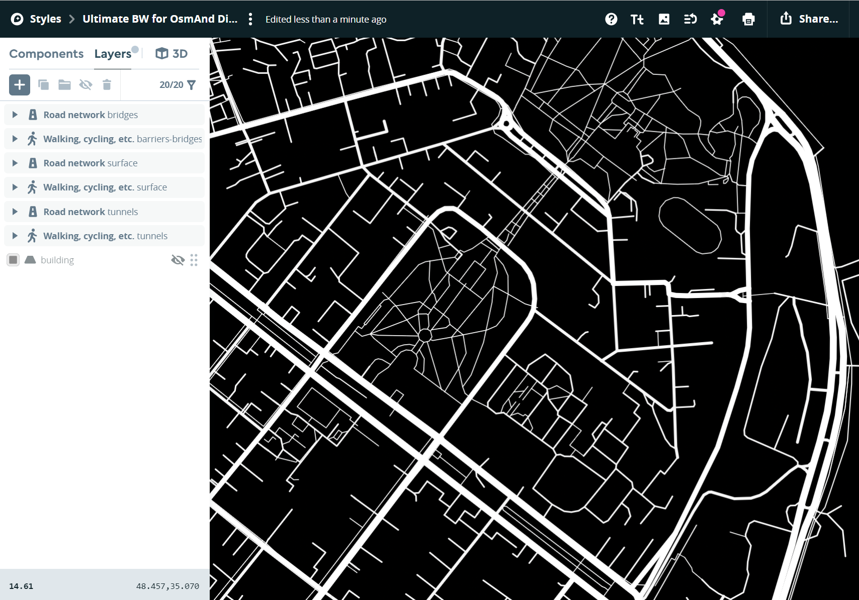
I included Mapbox SDK to my app because I already knew it was a very advanced OpenStreetMap viewer. In the Mapbox Studio, I created an ultimate black-white theme with only roads, sidewalks and trails and used the theme to get a fixed 200x200 snapshot in the app and send it to the display.
Wireless frame transfer from the app worked well too, it took around 6 seconds per frame, which, surprisingly, was not a big difference from the 4 seconds required for a direction. Hence, I made sure the live map display is possible.
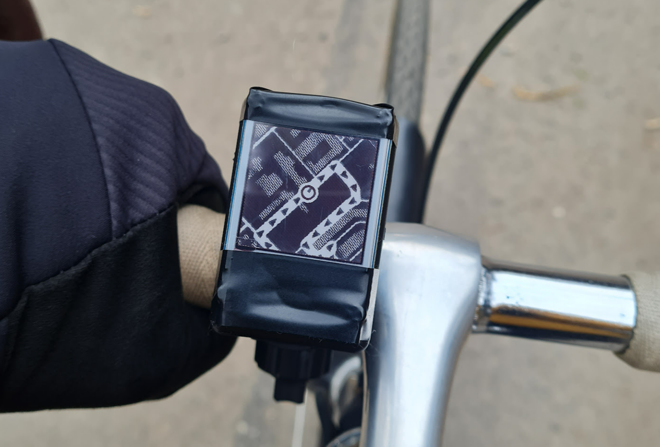
Second version. Live map. Success
Feature scope for the second version was the following:
- The display shows the map with my location. The map is minimalistic and contains only roads, sidewalks and trails;
- It is possible to add a track to the map. The track is shown with direction arrows
The map works offline.
In the Android app I implemented another foreground service, that subscribed to the GPS location updates and used Snapshotter from the Mapbox SDK to capture map frames. The Snapshotter class is very simple and doesn’t allow much control, so I extended it with the reflection. I tested the map at home using a location simulator app, and it worked surprisingly well. After a few walks outside with the display, I was pleased with the results.
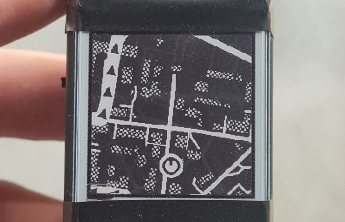
To add more clarity to the map, I decided to include buildings to the map style. Because the display does not support shades of gray, I used striped pattern fill for the buildings layer, fortunately Mapbox supports it.
I quickly added a GeoJSON track overlay to the map. The actual track was included in the app resources and there were no way to change it without rebuilding, but it was enough for a test ride. I made a track with multiple turns and loops across a nearby neighborhood and started my first test ride with high hopes.
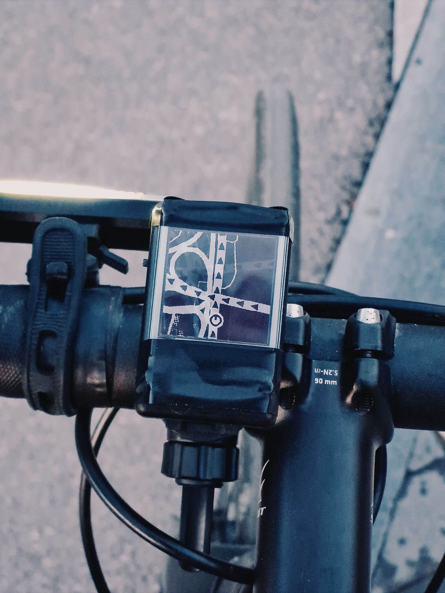
Riding with a map instead of turn directions was a huge step forward. I only missed a turn once, at the start, but then I had to use buildings as landmarks. “Turn after this L-shaped building you see on the right” is a totally clear direction you give yourself, looking at the map and comparing it to what you see around you.
After having two more test rides, I found that on high speed upcoming turns became visible too late. I decided to extend the display area used to show the upcoming route by making the map rotate according to the bearing and moving the location marker to the bottom. Having the map changing the rotation, the striped pattern of the buildings looked ugly at particular angles, so I replaced it with a circular dithering.
There was still the display delay issue – whenever you got a frame shown on the display, the location had been already outdated by 6 seconds. I wondered if a simple interpolation can solve it, and decided to try – instead of sending the actual location, I implemented sending of the approximate location if continue moving with the same bearing and speed for 6 seconds. It may sound counterintuitive, but this naive cheat actually reduced the inaccuracy – instead of the location being outdated for all the time, it became inaccurate only on turns, when you change the direction and the interpolation fails. But when riding straight, the cheat results in seeing your actual location once the frame is shown, as if you looked at the phone real-time navigator.
I implemented a proper import of GeoJSON tracks into the app from the device files. Then I added a second way, which is the most convenient for me – import by opening the BRouter Web route URL, so I can skip GeoJSON file downloading.

To make the map work offline, I used OfflineManager from the Mapbox SDK. It was surprisingly easy to download all the required area tiles when importing the track. To handle the situation when the device is offline and you are riding beyond the downloaded area, I implemented display of connection errors on the display. I made a test offline ride and found out that without the connection the location accuracy significantly degraded, although the map was showing correctly during the whole ride. It was an easy to fix though, as I only replaced the “PRIORITY_BALANCED_POWER_ACCURACY“ location request priority with the “PRIORITY_HIGH_ACCURACY” one, and forced the use of GPS signal.
Conclusion
I finally got what I was looking for – a useful bike navigation helper. Now I can explore new areas and don’t get lost or have to stop at every junction to check the route. This was my first portable wireless device, and although it is very simple and far less fancy than the products I took an inspiration from, I consider this project a success and a great experience.
This project has brought me one of the feelings I really like – when you’ve successfully solved a practical life problem by making something yourself, whether it is an app, a device or even a useful spreadsheet. Hope my experience with the bike navigation display will help or inspire you with your own projects. I also want to give my deep gratitude to my wife for believing in me and not letting me give up in moments of disappointment.